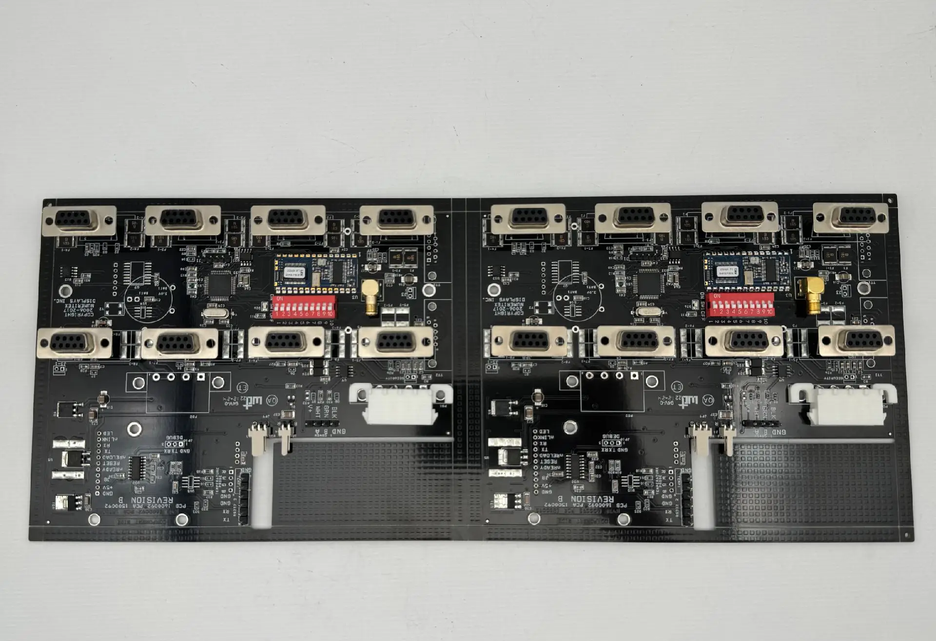
A lot of signal integrity simulation reports give the same recommendation: "Backdrill, and keep the stub length within 10 mils."
So the design engineer writes on the fab drawing: Backdrill, Stub ≤ 0.25 mm.
When it reaches the PCB fab, the process engineer just shakes their head.
Because that "leftover copper" you're trying to eliminate is exactly the hardest devil to remove on the manufacturing floor.
🔍 How much damage does a stub actually cause?
Anyone who has worked on high-speed design knows: that section of plated barrel that doesn't participate in signal transmission acts like a dangling capacitive/inductive antenna. Once your data rate hits 10Gbps, 25Gbps and above, it eats your eye diagram alive, reflection after reflection.
Theoretically, backdrilling is meant to remove this unused copper completely. In a perfect world, stub = 0.
But here's the reality: zero stub is physically almost impossible, and pursuing it aggressively brings a disaster.
⚙️ What exactly stands in the way?
1. Board thickness tolerance is an "inherent defect"
After lamination, a ±10% total thickness variation is perfectly normal. From the same batch, one panel could be 2.0mm thick, another 2.15mm. How can you program a fixed drill depth to achieve zero stub on all of them? Drill too deep, and you punch right through the signal trace or reference plane below.
2. The "safety margin" in depth-controlled drilling
To avoid puncturing active circuitry, the fab must leave a keep-out zone above the target layer. Typically at least 3-5 mils, to account for bit wear, thickness variation, and stack-up misalignment. This means the "zero stub" you designed on paper already has a gap reserved from the process side.
3. Layer misregistration and drill bit wander combined
The actual alignment between inner layer patterns and the drill file, plus spindle runout, will shift the drill tip's real landing spot. To avoid damaging adjacent traces, the safety distance gets even larger. The stub becomes even harder to reduce to zero.
🔎 What does a real production cross-section look like?
Go check a qualified backdrill cross-section at a PCB fab. The typical picture is: the drill tip just "kisses" the reference plane, but a tiny sliver of copper is intentionally left, or the stub fluctuates between 2-4 mils. A shop that can keep stub consistently under 4 mils across the whole batch is already top-tier manufacturing.
Those "lucky" zero-stub samples? Most likely shaved down some copper thickness from the layer below. Over time, that invites micro-shorts and CAF (conductive anodic filament) failures.
💡 Practical advice for designers:
· Never write Stub = 0. That's setting a trap for manufacturing. Specify a maximum acceptable value, like ≤ 8 mil or ≤ 10 mil, leaving a realistic process window.
· Consider plugging the backdrilled holes. Stub holes easily trap chemistry residues; without plugging or thorough cleaning, corrosion will keep eating away.
· Communicate with your fab early and ask for their "backdrill capability chart": minimum achievable stub, depth tolerance, registration accuracy. Build these process boundaries directly into your link budget.