
The positive and negative poles of a PCB can generally be distinguished through the following methods:
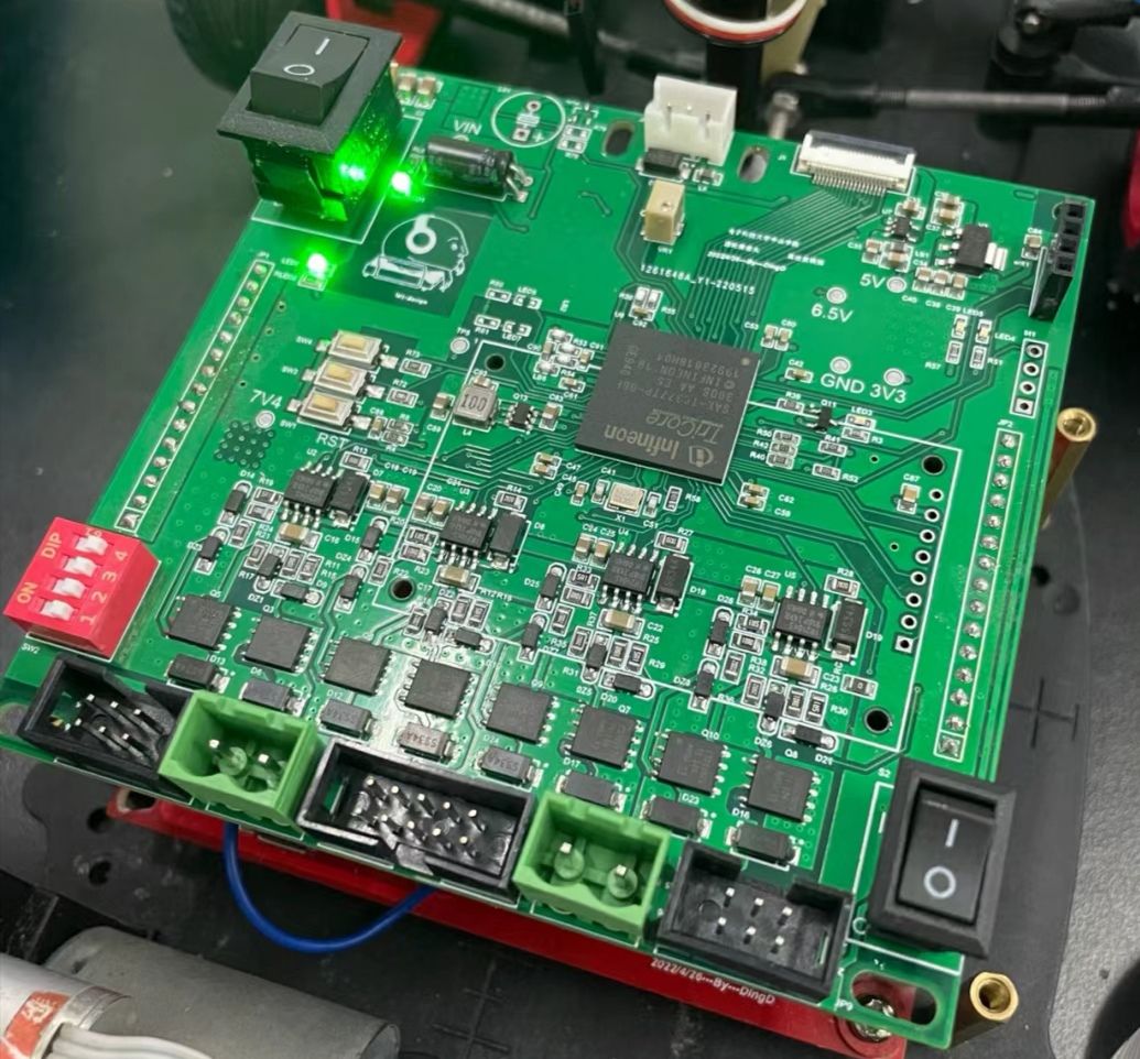
Judgment by silkscreen:
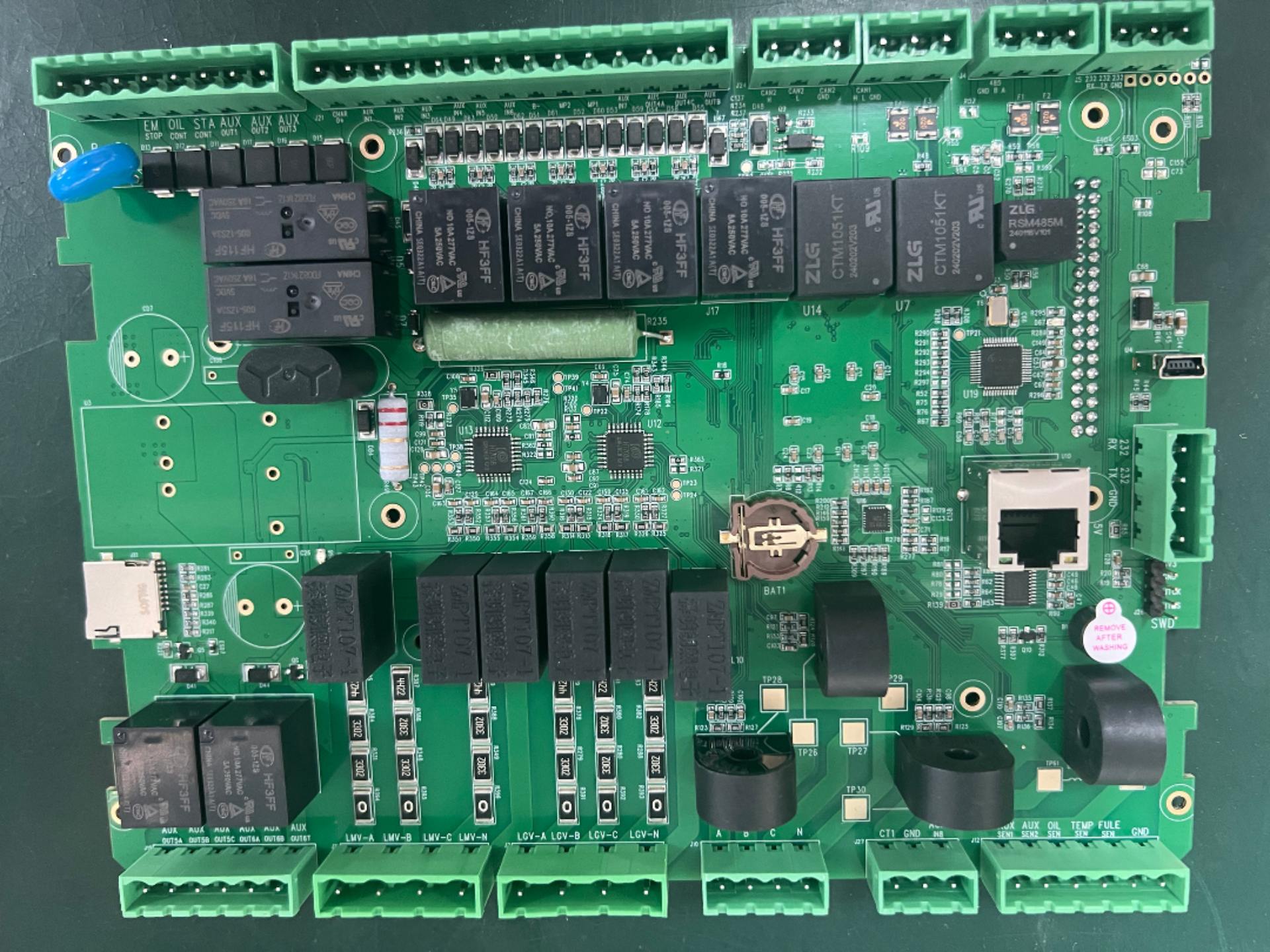
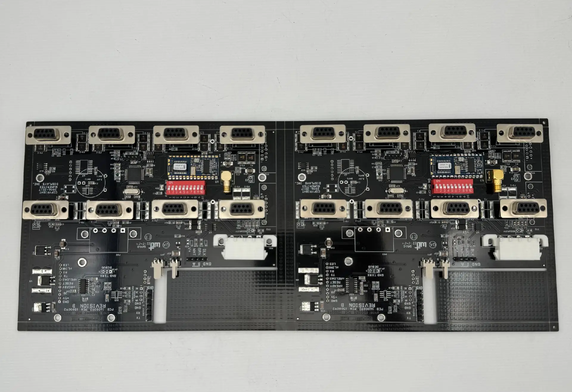
When an electronic engineer designs a PCB, silkscreen is usually used to mark the pin definitions of the interface part. For the positive and negative poles of the power supply, engineers generally use "V+" and "GND" for labeling. Among them, "V+" represents the positive pole, and "GND" is an abbreviation for the ground wire or zero line, representing the negative pole of the power supply.
Judgment by polarized components:
Polarized components such as electrolytic capacitors and diodes cannot be connected in reverse during use. Taking an electrolytic capacitor as an example, its positive pole must be connected to the positive pole of the power supply "V+", and the negative pole must be connected to "GND". The positive and negative poles of the circuit can be judged by observing the connection of the pins of these components.
Judgment by the copper-clad area:
In PCB design, in order to improve the anti-interference ability and reduce the ground wire impedance, the ground (GND) is usually electrically connected in the form of a large-area copper cladding. Therefore, by observing the large-area copper-clad area on the circuit board, it can be judged whether it is the ground wire (negative pole).
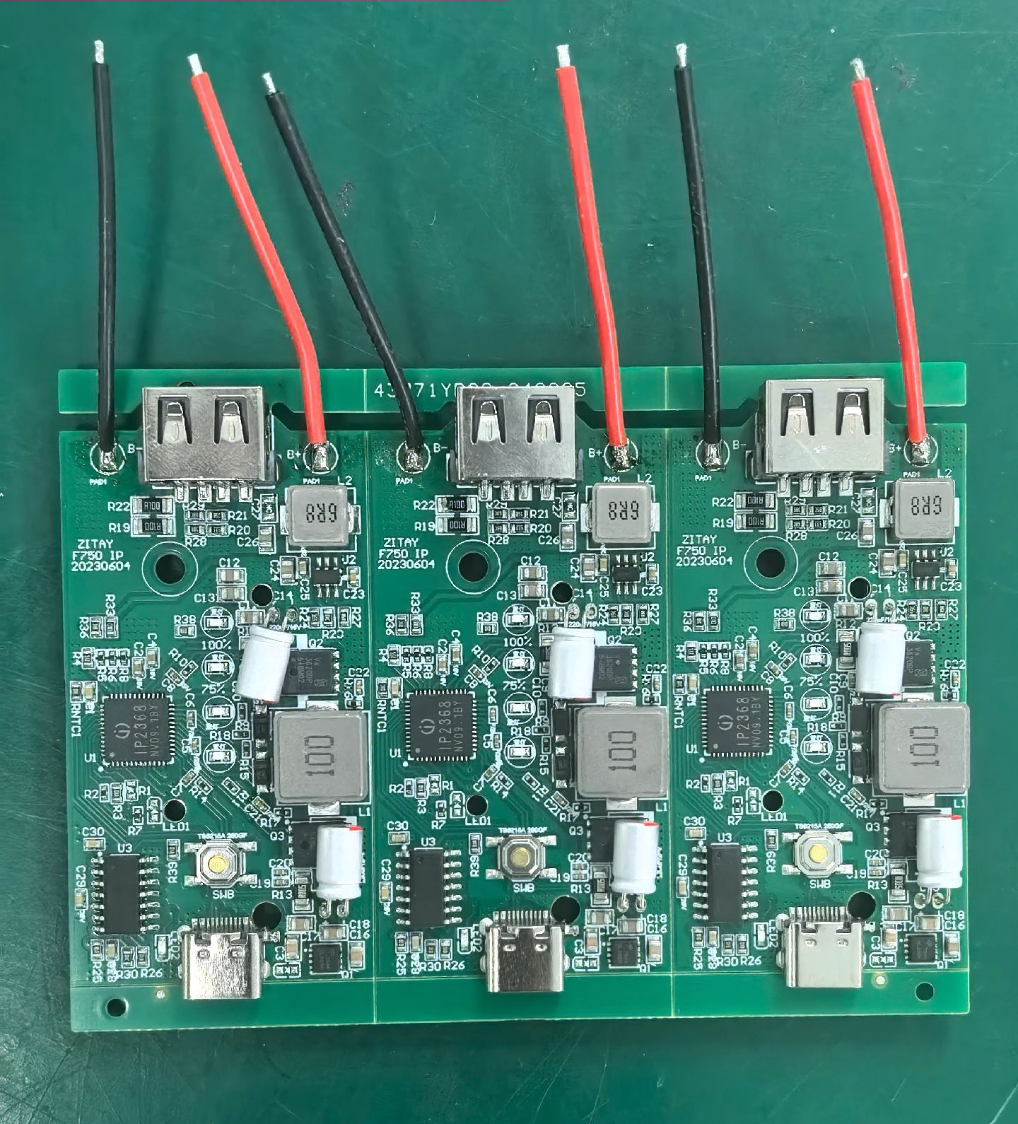
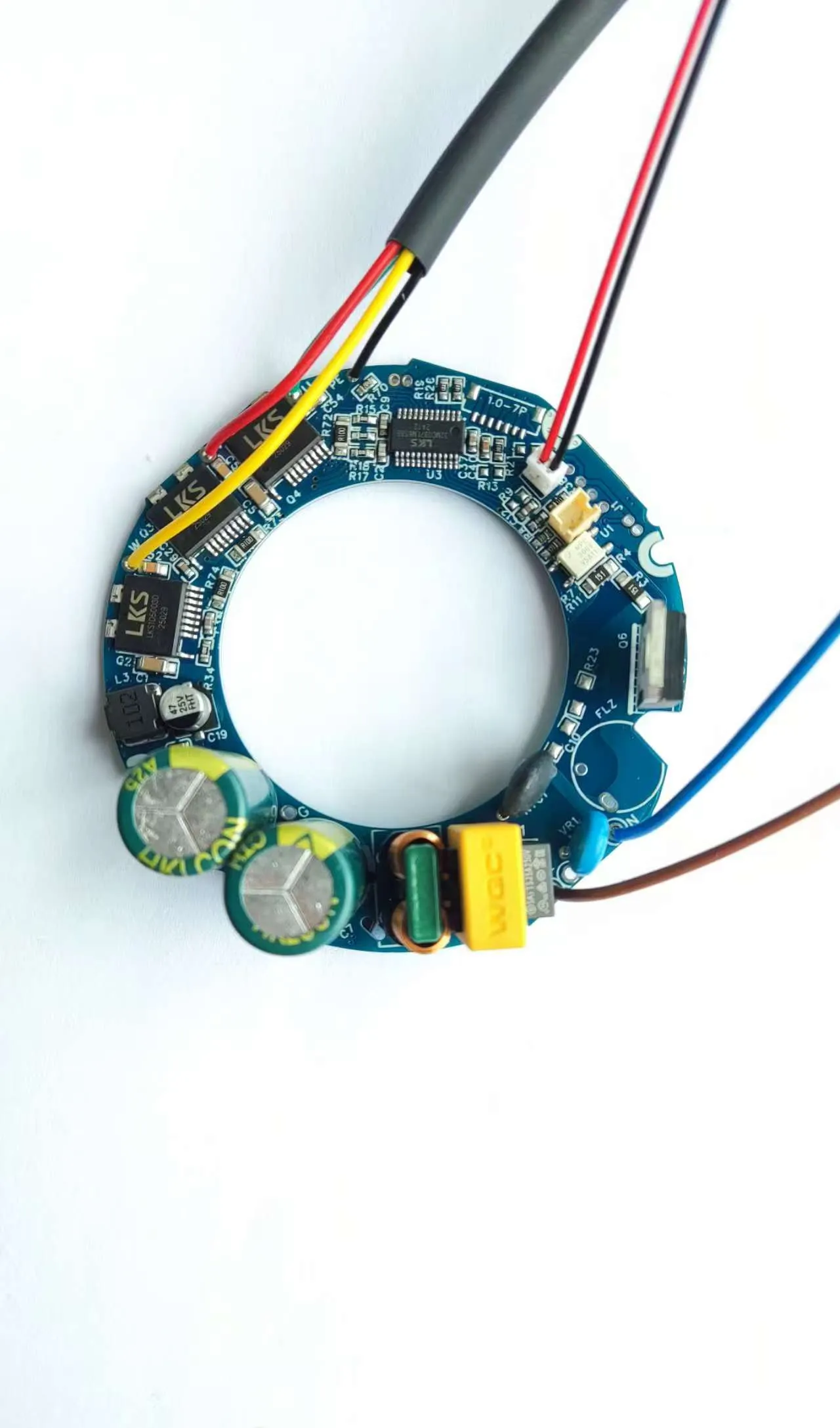
Marking and color coding:
Marks or symbols may also be used on the PCB to indicate the positive and negative poles. Usually, the "+" symbol is used to represent the positive pole, and the part with the "-" symbol or without a mark represents the negative pole. In addition, color coding is also a common method. For example, the positive pole part uses red lines or markings, and the negative pole part uses black lines or markings.
Judgment by chip pins:
If the pin sequence and power supply requirements of the chip are known, the positive and negative poles of the power supply can also be judged through the pins of the chip. However, this method is only applicable when there is only one power supply network. For circuit boards with multiple power supply networks, other methods need to be combined for judgment.
Judgment by the characteristics of diodes:
For ordinary diodes, the surface of the tube body can be observed. The end with a white line is usually the negative pole. For light-emitting diodes, the longer pin is the positive pole, and the shorter pin is the negative pole. If the lengths of the pins are the same, the smaller metal pole inside the light-emitting diode is the positive pole, and the larger sheet-like one is the negative pole.
Measurement with a multimeter:
Using a multimeter is also an effective method. Turn the knob of the multimeter to the continuity measurement gear, and connect the red and black test leads to the two pins respectively. If there is a reading, the end of the red test lead is the positive pole; if the reading is "1", the end of the black test lead is the positive pole (note that this method may vary depending on the specific model and settings of the multimeter).
In summary, the positive and negative poles on a PCB can be accurately determined by combining one or more of the above methods.


10585 View